
Running a laser with Marlin and the Ender 3 board
December 26th, 2021 (edited November 3rd, 2022)I recently started working on building a laser cutter/engraver. I wanted to use the Ender 3 v1.1.4 board and Marlin firmware because I already had them and was familiar with them. This didn't end up being too complicated, but it did require a few unexpected changes, which I'll document here. This isn't a step-by-step, just a summary of what worked for me.
I'm not an electrical engineer. This process worked for me, but I don't know if it will work you. Electricity is dangerous. Lasers are dangerous. Wear appropriate laser eye protection before powering the board with a laser connected.
You'll need to know how to build and upload firmware to the Ender 3 board to follow this. I have a little bit of info about that here.
I started with Marlin configured to run the Ender 3 Pro as a 3D printer. It's possible to run a laser in this configuration by plugging it into FAN1, the header for the part cooling fan. This is a 24V PWM signal with a pretty low frequency that you can probably increase by uncommenting FAST_PWM_FAN. However, I wanted Marlin to actually understand that this is a laser to improve the LCD interface and make sure I'm getting anything Marlin can do to optimize the results. So the first thing I did was just take a pass through 'Configuration.h' and 'Configuration_adv.h' making the obvious changes (diffs):
- Commenting/disabling the extruder axis
- Disabling the heaters and temperature sensors
- Disabling the status screen images except STATUS_CUTTER_ANIM
- Most importantly, enabling LASER_FEATURE and LASER_POWER_INLINE
This will actually work just work as far as Marlin is concerned, but I didn't know that at this point, because Marlin is actually no longer sending the laser PWM signal to the FAN1 header. This is because it would like to use the chip's faster hardware PWM for the laser instead of the slower software PWM it uses for the fan. Instead, it's actually moved the X stepper to the E stepper header, and it's sending the laser signals to the X stepper driver. For more info on this, see the bottom of 'pins_SANGUINOLOLU_11.h'.
Unfortunately we can't pick those signals up from the X stepper header because there's a stepper driver between the header and the board, and we can't easily remove the driver on this board (unlike some other boards that have socketed drivers). We have to follow the traces and find another spot on the PCB to pick it up. The laser PWM is configured in 'pins_SANGUINOLOLU_11.h' to come from pin 16 (PD7) on the microcontroller. I used the microcontroller datasheet to locate that pin, then used the PCB images from GitHub to follow the trace. I highlighted the trace in green below, and chose the via marked in red as the best place to insert a wire.
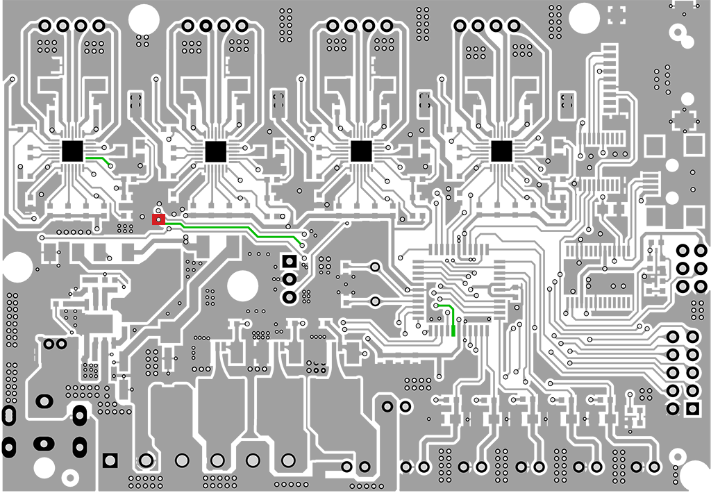
Power up the board with just the LCD attached and use a voltmeter to test the voltage between the via and ground with the laser on and off to make sure you have the right one. I cut the end off a female Dupont connector (28 AWG) and soldered it through the via.
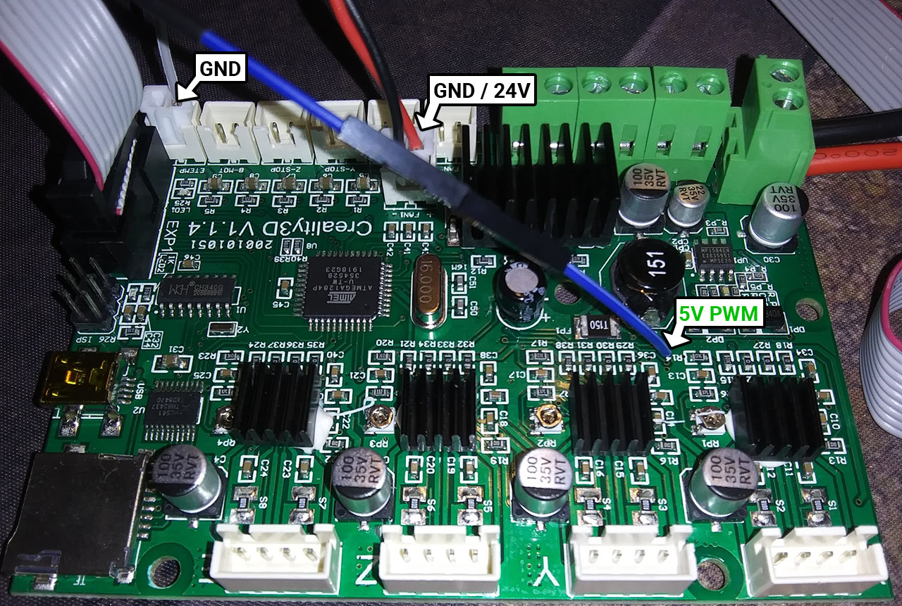
I'm using a 24V laser, so I'm giving it 24V from the FAN1 header. I commented the FAN_PIN definitions from Marlin in order to get an always-on 24V from the fan headers. You could probably pick up 5V from an unused two-pin header or 12V from the bed terminals if that's what your laser requires.
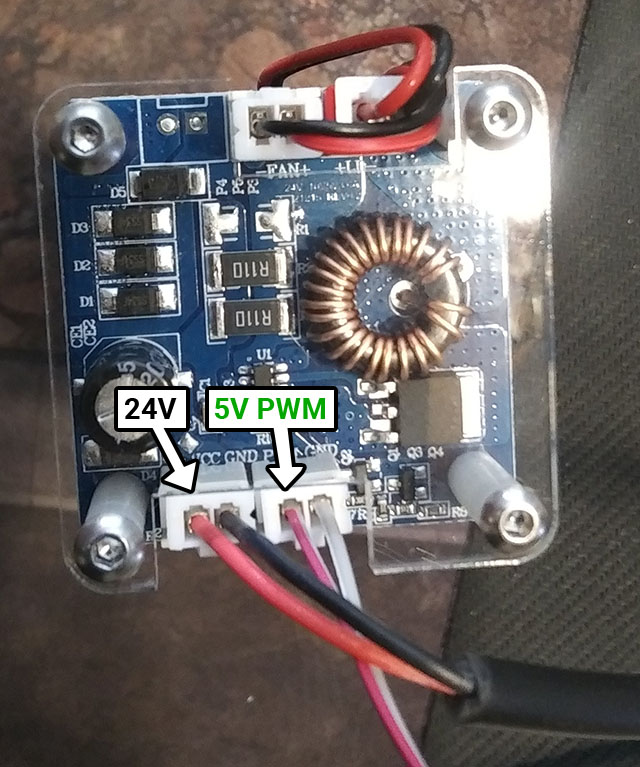
I tested the laser using this wiring, and it was on when enabled, off when disabled, and respected the configured power output percentage, so I think the electronic configuration is good to go.